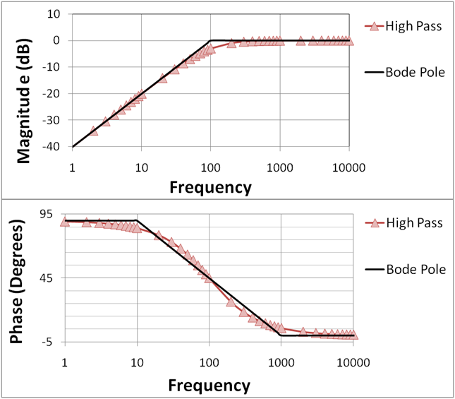
Bode magnitude plots nyquist
Table of Contents
Table of Contents
Are you struggling with drawing bode plots or finding a step-by-step guide to create one in PDF format? Look no further, as we have got you covered. In this post, we will share a simple guide on how to draw a bode plot step by step in PDF format that will make the process easy and effective for you.
If you are an electrical or electronics engineering student, then you know that bode plots are an essential part of your curriculum. However, the process of drawing them by hand can be time-consuming and error-prone, even with the help of software tools. Therefore, it’s crucial to have a step-by-step guide in PDF format that can help you save time and effort while ensuring accurate results.
The first step of drawing a bode plot is to understand the frequency response of the system. Bode plots are a graphical representation of the frequency response of a system, which is used to determine its stability and other important characteristics. Therefore, it’s essential to have a good understanding of frequency response theory before diving into the drawing process.
Next, you will need to create a logarithmic scale for the frequency axis and the magnitude axis. After that, you can sketch the asymptotic Bode plot by finding the corner frequencies and the slopes of the transfer function. Once you have the asymptotic Bode plot, you can sketch the exact Bode plot by adding the poles, zeroes, and breakpoints of the transfer function.
How to Draw a Bode Plot Step by Step PDF Guide
If you are looking for a step-by-step guide on how to draw a bode plot in PDF format, then you have come to the right place. Our step-by-step guide is easy to follow and includes detailed explanations of each step, along with illustrations to help you understand the process better.
 The guide covers the following topics:
Bode Plot Basics
In this section, you will learn the basics of Bode plots, including the frequency response of a system, logarithmic scales, Bode plot components, and phase shift.
Sketching the Asymptotic Bode Plot
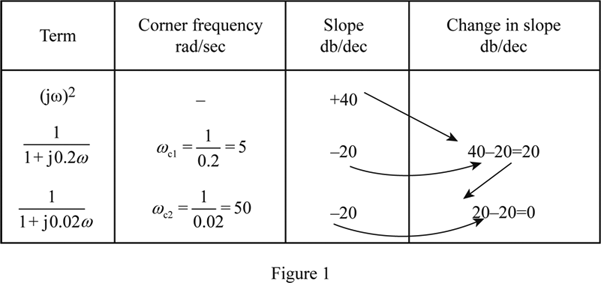
This section covers the process of sketching the asymptotic Bode plot, including finding the corner frequencies, determining the slopes of the transfer function, and drawing the Bode plot asymptotes.
Sketching the Exact Bode Plot
This section covers adding poles, zeroes, and breakpoints to the asymptotic Bode plot to sketch the exact Bode plot of the system.
Using the PDF Guide
The step-by-step PDF guide can be used as a reference while drawing Bode plots by hand. You can print the guide or keep it in digital format to refer to it whenever you need it. The guide includes examples and illustrations that demonstrate the process, making it easy to follow.
Common Mistakes to Avoid While Drawing Bode Plots
While drawing Bode plots, it’s essential to avoid the following common mistakes:
- Forgetting to use logarithmic scales for the frequency axis and the magnitude axis.
- Not identifying the corner frequencies correctly, which can result in incorrect slope values.
- Not adding poles, zeroes, or breakpoints to the asymptotic Bode plot, resulting in an incorrect exact Bode plot.
Question and Answer
What are Bode plots used for?
Bode plots are used to represent the frequency response of linear systems. They are used in control engineering, signal processing, and circuit analysis to determine the stability, gain margin, phase margin, bandwidth, and other important characteristics of a system.
What is the difference between an asymptotic Bode plot and an exact Bode plot?
The asymptotic Bode plot is sketching by finding the corner frequencies and determining the slopes of the transfer function. It provides an approximation of the Bode plot of the system. On the other hand, the exact Bode plot is drawn by adding poles, zeroes, and breakpoints to the asymptotic Bode plot. It provides more accurate results.
What is the purpose of using logarithmic scales in Bode plots?
Logarithmic scales allow us to represent a wide range of frequencies and magnitudes on a single graph. They make it easier to see the low and high-frequency behavior of a system on the same plot.
What are the common mistakes to avoid while drawing Bode plots?
The common mistakes to avoid while drawing Bode plots are:
- Forgetting to use logarithmic scales for the frequency axis and the magnitude axis.
- Not identifying the corner frequencies correctly, which can result in incorrect slope values.
- Not adding poles, zeroes, or breakpoints to the asymptotic Bode plot, resulting in an incorrect exact Bode plot.
Conclusion of how to draw a bode plot step by step pdf
Drawing Bode plots can be challenging, but with the help of our step-by-step PDF guide, you can simplify the process and avoid common mistakes. Remember to always use logarithmic scales and identify the corner frequencies correctly to get accurate results. We hope that this guide will help you in understanding and creating Bode plots better.
Gallery
Mechanics Of Drawing BODE Plots By Hand - An Example - YouTube

Photo Credit by: bing.com / bode plots drawing hand
Describe What Is Meant By Frequency Response In Regards To The The

Photo Credit by: bing.com /
Bode Plot Example | Bode Diagram Example MATLAB | Electrical Academia

Photo Credit by: bing.com / bode matlab magnitude margin
Bode Plot EXAMPLE - YouTube

Photo Credit by: bing.com / bode plot example
Bode Plot Examples With Solutions | How Do You Make A Bode Plot

Photo Credit by: bing.com / bode magnitude plots nyquist


